Considering Scaling Up for More Output? Follow These Tips
Keep these calculations handy when you are trying to decide whether a bigger extruder will get you the output you need.
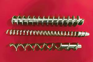
Sooner or later, every processor considers scaling up their extruder sizes for more output. It’s well known to extruder designers how increasing the diameter of the barrel bore boosts potential output. But to many others it’s not as well understood. Output at open discharge (no head pressure) can be closely estimated using the old “drag flow” or output equation, which for single screws is:
Drag Flow = [0.95 × π2 × D2 × H × (L-W/L) × RPS × (sin Ѳ × cos Ѳ)] 1/2
Where:
D = Bore diameter, in.
H = Metering channel depth, in.
L = Flight lead, in.
W = Channel width, in.
RPS = Screw rpm/sec (rotations/sec)
Ѳ = Helix angle, degree
Notice that the bore diameter (D) is squared in the equation. So, if we keep all the other terms the same, using the same polymer, and increase just the bore diameter from a 3 in. to 4 in., what would the potential output difference be? The effect of head pressure must be considered first, as it subtracts from the output.
Squaring just the bore size and leaving all the other terms the same results in (4)2/(3)2 = 1.77. That means the potential output of the 4-in. extruder is at least 77% greater than that of the 3-in. extruder.
However, you also need to scale up the channel depth (H) for the larger screw diameter to maintain similar shear rates, melting rates, melt temperatures and melt quality. Designers have several methods for scaling up the channel depth to match the scale-up of the bore size. Basically, it’s matching the shear rates in the metering channels in particular. Using a channel-depth estimate for scaling up when processing identical polymers would increase the projected output by a further 1.3:1 for a total of (1.77 x 1.3) = 2.3. So going from a 3-in. to a 4-in. bore size could be expected to increase the output more than twofold.
This approach has been used many times in the past to get a good first estimate for scaling screw outputs. I have used it in designs from 3 lb/hr to 120,000 lb/hr for screws varying in diameter from half-inch to 18 in., with good results. Again, this is an estimate and not the complete answer, but it is very useful. Assuming the same L/D, there are a number of additional factors that need to be considered in the final design, such as the geometry of the feed and compression sections, the head pressure and mixing.
The smaller the scale-up/scale-down, the more accurate it is.
Once the output is estimated, it can also be used to calculate the required drive power to achieve a similar motor load for the scaled design. Power is a closely defined quantity almost always monitored on an extruder, and since an extruder is a relatively closed system the power to heat and melt the polymer with a properly scaled screw design is largely proportional to the output.
Once screw rotation begins, almost all the energy entering the polymer is from shear heating due to screw rotation and not from heat conducted from the barrel, because of the poor thermal conductivity of polymers. If that weren’t true you could simply turn on your barrel heaters and start the screw as soon as they reached setpoint instead of waiting a few hours until it “soaked in.”
The smaller the scale-up/scale-down, the more accurate it is because very large steps may not account for some differences in thermal heat transfer, and in very small screws barrel heating can contribute more of the energy input because of the small distances for heat transfer.
ABOUT THE AUTHOR: Jim Frankland is a mechanical engineer who has been involved in all types of extrusion processing for more than 50 years. He is now president of Frankland Plastics Consulting, LLC. Contact jim.frankland@comcast.net or (724) 651-9196.
Related Content
Part 2 Medical Tubing: Use Simulation to Troubleshoot, Optimize Processing & Dies
Simulation can determine whether a die has regions of low shear rate and shear stress on the metal surface where the polymer would ultimately degrade, and can help processors design dies better suited for their projects.
Read MoreWhat to Know About Your Materials When Choosing a Feeder
Feeder performance is crucial to operating extrusion and compounding lines. And consistent, reliable feeding depends in large part on selecting a feeder compatible with the materials and additives you intend to process. Follow these tips to analyze your feeder requirements.
Read MoreOptimizing Pack & Hold Times for Hot-Runner & Valve-Gated Molds
Using scientific procedures will help you put an end to all that time-consuming trial and error. Part 1 of 2.
Read MoreBack to Basics on Mold Venting (Part 1)
Here’s what you need to know to improve the quality of your parts and to protect your molds.
Read MoreRead Next
Beyond Prototypes: 8 Ways the Plastics Industry Is Using 3D Printing
Plastics processors are finding applications for 3D printing around the plant and across the supply chain. Here are 8 examples to look for at NPE2024.
Read MoreLead the Conversation, Change the Conversation
Coverage of single-use plastics can be both misleading and demoralizing. Here are 10 tips for changing the perception of the plastics industry at your company and in your community.
Read MoreFor PLASTICS' CEO Seaholm, NPE to Shine Light on Sustainability Successes
With advocacy, communication and sustainability as three main pillars, Seaholm leads a trade association to NPE that ‘is more active today than we have ever been.’
Read More.jpg;width=70;height=70;mode=crop)


