Injection Molding: Improved Flatness Analysis in Upgraded CAE Molding Simulation Package
More precise and quantitative flatness analysis of injection molded parts is possible with the new version of Moldex3D CAE molding simulation.


FIG 1 Definition of flatness.
Flatness is a key quality factor in many plastic parts, from “fit and finish” in automotive or appliance parts to essential functionality of electrical connectors, cellphone housings, optical lenses and reflectors for heads-up displays—especially when molded parts are assembled to mating components. Therefore, flatness prediction, especially in the early design phase, is vitally important to manufacturers.
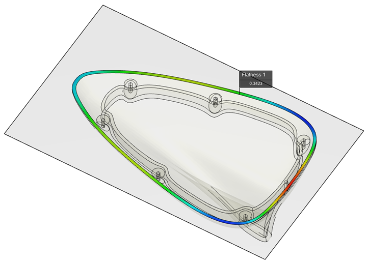
FIG 2 Flatness prediction of assembly surface of an automotive antenna cap.
More precise and quantitative flatness prediction is one of many enhanced features in Moldex3D 2020, the brand-new update of injection mold analysis from of Taiwan, which incorporates Moldex3D Studio, the new and all-inclusive pre- and post-processing user interface. Computation of flatness analysis uses the least-squares method to calculate the best-fit plane of the specified area after deformation, and then finds the two planes that are parallel to this best-fit plane and completely contain the measurement area (Fig. 1).
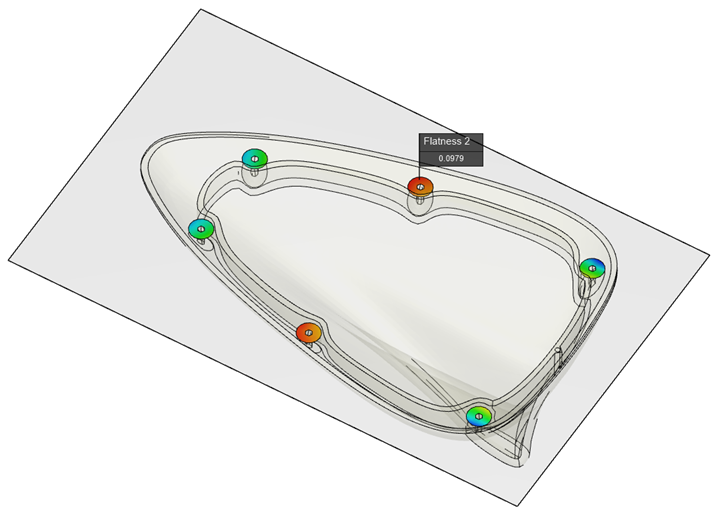
FIG 3 Flatness prediction for individual assembly studs in automotive antenna cap.
Using the example of an automotive antenna cap, Moldex3D can model the cap screwed to a plane and measure the flatness of the assembly surface at any point along that surface (Fig. 2). It’s also possible to measure the flatness of individual fastening stud surfaces (Fig. 3). Users can view the flatness deformation trend by magnifying the deformation with Moldex3D’s deformation analysis feature (Fig. 4). In addition, Moldex3D 2020 can perform a series of flatness analyses as part of a virtual DOE with different molding parameter settings (Fig. 5) to help users optimize the molding process to minimizes the risk of flatness deformation.
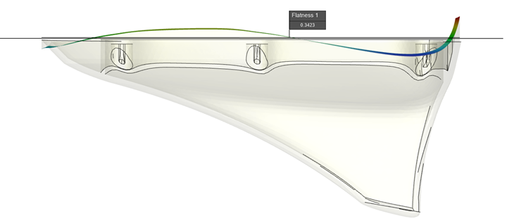
FIG 4 Magnified deformation analysis of antenna cap.
Sources of the software, training and/or custom CAE analyses include EPS FloTek and Kruse Analysis.
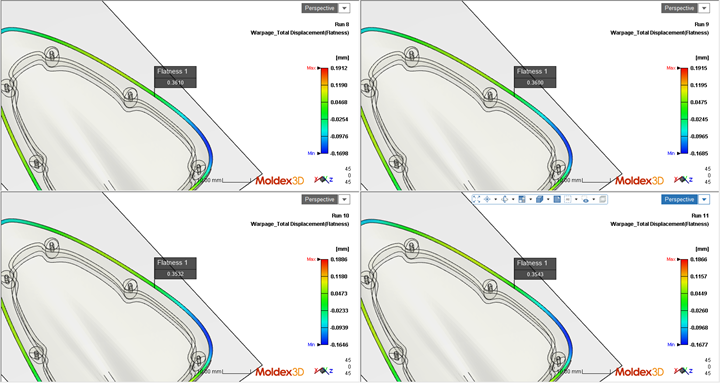
FIG 5 Flatness comparison under different molding parameter settings.
Related Content
-
How to Achieve Simulation Success, Part 2: Material Characterization
Depending on whether or not your chosen material is in the simulation database — and sometimes even if it is — analysts will have some important choices to make and factors to be aware of. Learn them here.
-
Hasco Marks a Century in Mold Components, Mold Bases and Hot Runners with Cake and New Technologies
NPE2024: Cake, drinks and the unveiling of a new North American website providing online ordering in the U.S. and Canada for the first time are just some of the things happening at Hasco’s booth as it brings its year-long centennial celebration to Orlando.
-
MPM’s Second Act: Keeping Injection Molding, Moldmaking in the Midwest
Larry Austin’s 35 years at a highly successful injection molding company inform much of what he does and doesn’t want in his second act in plastics owning an injection molding company.